- (513) 305-0700
Airflow measurement stations help ensure the optimum circulation of air throughout building HVAC applications. But these systems are only useful if the information they provide is consistent and accurate. And, as any building designer, owner, or maintenance technician will tell you – this isn’t always the case. Based on our experience, here are the seven most common reasons for the underperformance of airflow measurement stations.
Have you ever experienced an airflow measurement project that did not perform to your expectations? If so, I would be willing to bet that the problem was not easy to resolve. These types of challenges do not go away quietly or resolve themselves. The HVAC environment provides many challenges for the correct application, installation and operation of airflow measurement equipment. Thankfully, there are several technologies available that, when properly selected can perform very well.
AEB Technologies has more than 20 years of experience in the HVAC airflow industry and we have encountered many challenges in this essential application. The most important thing to remember is that airflow measurement is not a one size fits all application. We have taken our many years in the field experience to provide you with a list of the top seven most common challenges of airflow measurement. This includes why some technologies underperform, get a bad name, and otherwise have not met the expectations of the owners and designers.
In order of most common occurrence:
1. Poor Accuracy or Erratic Readings (Tight Applications with Limited Straight Run)
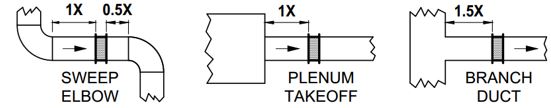
Straight runs, straight runs, straight runs! The accuracy of your installation depends upon finding the best locations for the airflow measurement stations. These are the distances that are tested by the factory and represent the greatest opportunity to good accurate flow measurement.

You will have the best results from your flow measurement equipment if you have, or can find, the required straight runs. Conversely, locations such as Fan Inlets, Plenums, and Rain Hoods do not have the required straight runs and are more difficult to measure consistently and accurately.
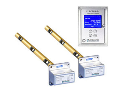
Note: Some technologies such as the OAM II from Air Monitor do not require any straight runs. They can still deliver great accuracy (+/- 5% AMCO certified) and work exceptionally well for OA applications where minimal straight runs are often difficult to achieve.
2. Airflow Measurement Station Not Reading (Low Flow Applications)
Velocity is king when we talk about flow measurement and good accuracy. The slower the air is moving the more challenging it becomes to get consistently reliable and accurate data.
There are two main reasons for this.
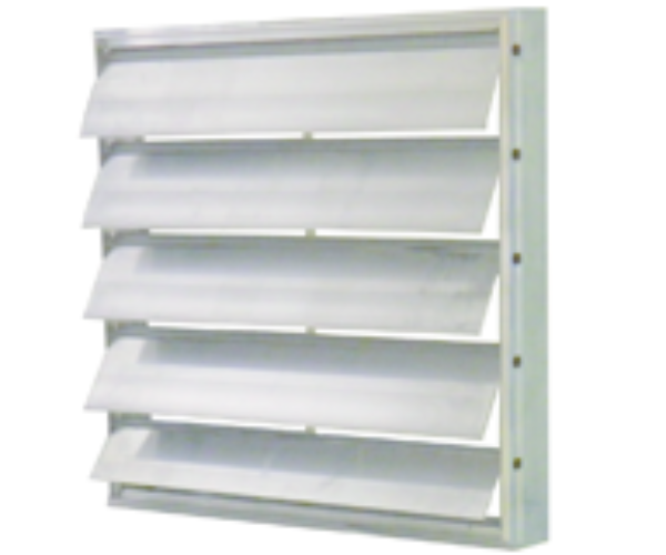
When working on OA applications designers should focus on sizing the louver and damper sizes to maintain a reasonable flow velocity (200+ fpm). This is particularly challenging when we have an AHU with a min OA and Economizer dampers. When only the OA damper is open the total available area at the louver is unchanged and is now considerably larger than the OA damper opening alone. The OA damper generally being much smaller than the Economizer damper may represent only 1/3 of the available flow. This will reduce the “total flow” velocity through the total available area of the louver from 3-400 fpm to 100 fpm or less which is extremely difficult to accurately and reliably measure.
One simple solution for this application would be to bifurcate the total OA inlet so that the OA damper and the Economizer damper would each have their own louver. This would separate the two flows maintaining their respective design velocities and produce a much more favorable application for good flow measurement.
3. AFMS Does not Match the Size of the Duct
It’s very challenging to properly install AFMS probes that are 3” too wide for the duct. To the best of my knowledge there no acceptable “field modifications” that will allow improperly sized probes to be installed. Installed probes or stations that are too long or too short will NOT produce quality results. Additionally, there is no market for returned airflow stations – so this practice is best when avoided!
 I doubt that this is news to many of you but dimensions on drawings do not always match those of ductwork in the field. Even the best engineer cannot always locate every obstruction. Consequently, ductwork sometimes needs to be modified to fit.
Equally troubling is discovering that designated installation locations do not meet the manufacturer’s guidelines. Well, if you can’t afford a duct stretcher you may be served by reaching out to your local manufacturers rep. A visit from a qualified representative will help locate every station in the project and take all the field measurements requirements for the final ordering. A good rep will do this at no charge; and this step can be detailed in the engineering specifications. While this does require a little extra time and effort, it will take considerably more time, effort, and expense to learn after the fact that thousands of dollars of airflow probes will have to be saved for another project!
4. High Maintenance (Dusty Environments)
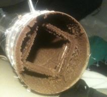 AFMS re not designed to be coated or covered in dust and lint. These items of debris are often found on the return side of HVAC systems, particularly those in hospital environments. Both Thermal and Differential Pressure technologies have challenges here and both will require periodic cleaning to prevent failure. Unfortunately, there is no silver bullet for this problem other than managing expectations. In important areas it will be best if some preventative maintenance measures are put in place.
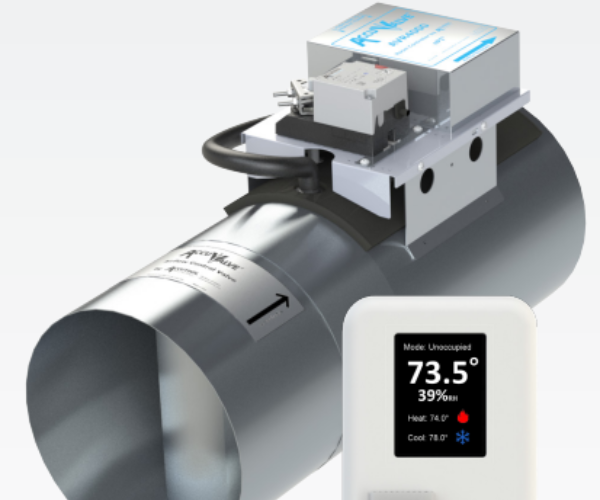
The best technology for return side ducts that I am aware of is the CRC-CLV or Closed Loop Airflow Control valve from Critical Room Control (CRC). These valves have high repeatability, accuracy and turndown. They are true Venturi valves with a differential pressure manifold that is very resistive to dust collection. This helps them last for many maintenance-free years. However, because these valves are designed for critical applications, they may not be the best option for all return ductwork.
5. Erratic AFM Readings During Inclement Weather (or AHU Humidification Cycles)
Have you ever added a “spool” piece or a short straight piece of duct in between an AHU and a rain hood? This is a common solution for contractors who have attempted to install Thermal Dispersion technology in a hood and could not get it to perform satisfactorily.
There are three major challenges to consider when selecting an airflow measurement technology for installation in a rain hood or other non-ducted application (such as fan-inlets or in front of large louvers).
6. Difficulty Maintaining Building Pressure (Looking for Increased Accuracy)
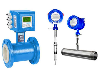
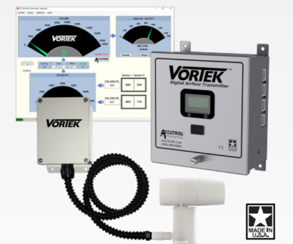
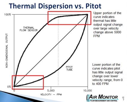
Are you looking for high accuracy airflow measurement? When high accuracy is important sensor density matters. You will achieve the highest, most reliable accuracy with a Thermal Dispersion probe array in straight runs of ductwork. In general, the more sensing points (i.e., sample points) the better the overall accuracy.
That is not to say that differential pressure (DP) and pitot tubes cannot be highly accurate. However, if high accuracy is required with DP measurement it would be best to use in high velocity applications. Fan inlets come to mind when I think about high flow velocities – and in these applications DP (pitot tubes) is recommended over Thermal when high accuracy is paramount. This is one location where the average taken by the pitot tube, combined with a high-quality transmitter will be preferred over Thermals 1 or 2 sensing points.
Note: For all DP applications it is highly recommended to specify a high quality, high accuracy DPT with auto zero to ensure great accuracy (comparable to thermal) and low maintenance over the long run.
7. Poor Tracking and Frequent Rebalancing (Long Term Stability)
No owner enjoys having a building turned over to discover a few months later that the instrumentation is struggling, and the construction warrantee has just expired. One of the biggest concerns with airflow measurement stability is drift. Simply stated, the drift is the amount that the current 0 measurement for sensors may move over a period of time. While its usually small it can and does grow into considerable error over a period of months or years.
DPT quality, extreme temperature, time, and luck will determine how long it takes until your flow readings have left the realm of usefulness. Sadly, problems like this seem to persist for years on end and are repaired only when absolutely necessary. With today’s technologies a well-designed flow measurement system that includes an auto-zero transmitter will last for years and years before any issues arise with accuracy, or poor performance.
Note: Just FYI, Thermal Dispersion airflow stations experience very little drift over time and are extremely reliable.
Summary
In summary, there is no single airflow measurement technology that will work best for every application. The technology selected should match the needs of the building owner for accuracy, maintenance, reliability, and that of the application itself.
Hopefully the information above will help you reduce a few of these issues and improve the performance of your systems and buildings.

Questions?
Do you have questions about airflow measurement? Contact me (Joseph Moore) here or email me at jmoore@aebtech.com . I’m always happy to discuss your application and share my experience.