- (513) 305-0700
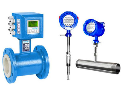
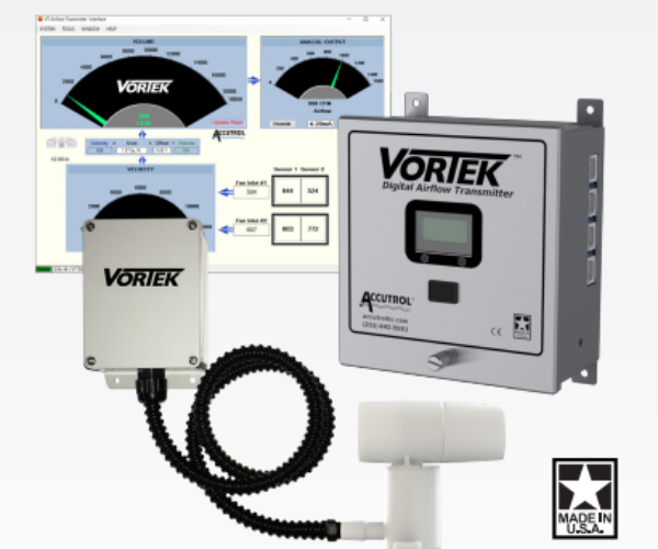
Employed in a variety of building applications, Electromagnetic Flow Meters measure the flow of conductive liquids through tubes and pipes. These flow meters use magnetic fields to measure the ion particles in fluid through a process known as electromagnetic induction.
This phenomenon is defined by Faraday’s Law – a law used to predict the interaction between a magnetic field and an electric circuit producing an electromotive force. You can about this in more detail here.
Common Grounding Errors
Like any piece of electrified equipment, proper installation and grounding of Electromagnetic Flow Meters is also critical from both a performance and safety perspective. If not correctly grounded, noise signals resulting from stray currents created from high voltage equipment, VFD’s, and other motors may resonate through the fluid and into the instrumentation. This disturbance can interfere with signals generated by the flow meter compromising reading accuracy.
According to Allen Kesselring, Senior Technical Support Engineer for ONICON, there are three common issues associated with grounding magnetic meters. These include meter body grounding points, ground connection points, and input voltage terminal grounding.
Meter Body Grounding
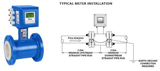
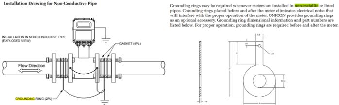
“Perhaps the most repeated error is related to the meter body grounding points. These points must be electrically bonded via ground wires directly to the pipe on both sides of the meter location,” he explained. In the case of non-conductive pipe connections Kesselring recommends the use of solid copper 16 or 18-gauge wire with grounding rings.
With conductive pipe, the meter liner is in contact with the pipe flange and serves as an insulator. With the exception of the flange bolts this electrically insulates the meter from the pipe and water. However, they proved almost no grounding because of the paint coating on the pipe and meter body. For this reason, it is so important to ground the meter body to the pipe. Doing this puts the conductive water in the pipe at the same electrical ground potential as the meter body and measuring electronics.
Ground Connection Points
Kesselring further explains that ground connection points can also contribute to grounding issues. “One of the above ground connection points must be connected to a valid electrical earth ground. This may include a main building electrical earth ground, or a suitable length ground rod that has been driven into the soil.”
Input Voltage Terminal
Another common issue involves grounding the input voltage terminal on the electromagnetic flowmeter. Kesselring points out that the earth ground should be connected to a valid electrical ground point, as would be used for the third prong ground on a power line plug. This is a power input safety ground, which is most important on flow meters that have 120VAC input voltages and is not an earth ground for the flow meter itself. On magnetic meter low voltage input display heads, however, connecting this earth ground is of minimal importance since a safety ground is not typically used with low voltage AC or DC applications.
The Dangers of Inexperience
Many who install Electromagnetic Flow Meters have limited knowledge of such instrumentation and the importance of proper earth grounding. As a result, grounding problems can often be traced back to human error.
“Unfortunately, it is common to attempt to earth ground a flow meter to a piece of electrical conduit, a piece of structural steel, the ground side of the input power supply or a control panel ground,” said Kesselring. “Electricity always takes the path of least resistance. So, an 8-gauge solid copper wire connected to a copper earth ground rod driven sufficiently deep in the earth is typically the lowest resistance path.”
Note that the use of rebar or steel rods as ground rods is not recommended as a long-term solution as these metals are prone to rust and corrosion.
Soil and Ground Rod Depth
Kesselring points out that the nature of the soil is a determining factor as related to the required depth for the ground rod.
“Moist compact soils provide the best earth grounding and the shallowest rod depth. Conversely, dry, powdery, sandy, or rocky soil provides the worst grounding condition and requires that ground rods be driven to a deeper depth.”
The National Electrical Code (NEC) requires all driven ground rods to be a minimum of 8 feet deep in the earth or if not driven, buried horizontally in a trench at least 30 inches deep. This is necessary to obtain the lowest possible resistance of the earth ground.
Multiple Flow Meters
When installing multiple Electromagnetic Flow Meters, it’s tempting to run ground wires from all meters to a single earth ground point. This is not recommended as some ground wire runs are long and follow paths near or over electrical noise producing devices such as pump motors, compressor motors, VFD drives, and high voltage power cables.
“Additionally, the longer the earth ground wire run, the greater the added resistance of the wire itself and the greater chance of the ground wire picking up noise and feeding it back to the flow meter instead of taking it to earth. The more devices you connect to the ground wire, the more chance you have of one device feeding electrical noise into the ground,” explained Kesselring.
Need Assistance?
Proper Electromagnetic Meter grounding is one of the most critical details surrounding this type of flow meter installation. This is true for both in-line and insertion style meters. Applications may vary and in addition to product performance, safety issues may also arise. If you would like more information on proper instrumentation grounding or have current issues that may be a result of improper grounding, please do not hesitate to contact me (jmoore@aebtech.com) or any other member of the AEB Team for assistance.