Refrigerant gases are literally the lifeblood of today’s air conditioning, refrigeration, and freezing technologies. Under controlled and monitored conditions these gases are safe and efficient. However, if not closely monitored and allowed to escape into the atmosphere, they can be extremely hazardous to both personnel and our environment.
To help ensure safety, ASHRAE (The American Society of Heating, Refrigerating and Air-Conditioning Engineers) mandates that each refrigerant machinery room be monitored for leaks. Specifically, ASHRAE section 8.11.2.1 states: “Each refrigerating machinery room shall contain a detector, located in an area where refrigerant from a leak will concentrate, that actuates an alarm and mechanical ventilation in accordance with Section 8.11.4 at a value not greater than the corresponding TLV-TWA (or toxicity measure consistent there with)…”
In addition to monitoring, further steps should be taken to ensure the safety of building occupants, maintenance personnel, and early responders. These include, among other precautions, external alarms, and the availability of self-contained breathing apparatus (SCBA).
Note:
The following article is based on information derived from Air Monitor
Corporation in a 2019 webinar “Yes You Can Accurately Measure Outdoor Airflow”.
At this article’s conclusion is a link where you may view the webinar in its
entirety.
Introduction
Drawing and conditioning outside air for heating, cooling and ventilation applications remains a standard practice for new constructions, refurbished and older buildings alike. But in order to ensure occupant safety and comfort, air brought in from the outside must be accurately measured. Additionally, managing outside airflow is critical in reaching energy savings goals, and regulations associated with today’s high-performance buildings.
Why
Measure?
Unlike
other utilities, outdoor air is mandated by code requiring a certain amount of
outdoor air to be delivered to a space. The American Society of Heating, Refrigerating and Air-Conditioning
Engineers (ASHRAE) publishes multiple documents and standards to help
ensure that ventilation health, regulatory, energy, performance, code and other
requirements are met.
ASHRAE regulations include:
ASHRAE 62.1: This is the standard for outdoor air quality and amount of outdoor dilution air brought into a building based on building size, type and occupancy. ASHRAE 62.1 has become the de facto standard for determining the amount of outdoor airflow required for a commercial building. This standard also provides guidance regarding how to balance the need for outdoor air versus the energy cost associated with conditioning that air. While this standard does not directly mandate airflow measurement – measuring airflow directly is the optimum way to ensure compliance.
ASHRAE 189.1: This standard governs the design and operation of high-performance green buildings. This standard incorporated 62.1 and mandates that airflow be measured and accurate at each system level device. Accuracy is the key; while measuring outdoor air is important, ensuring its accuracy is critical.
ASHRAE 90.1: This is the minimum energy standard defining the minimum energy efficiency requirements for the design and operation of new and existing buildings. While it does not directly mandate outdoor air, this standard relates to the operation and control of ventilation systems as they relate to climate zone, building size, type and so on.
Consequences
of Not Measuring Airflow
While
there are a variety of measurement technologies available today, most were
developed to operate in the confines of duct work. With many of today’s
commercial buildings being designed without OA duct (non-ducted), this creates
some hurdles for measuring outdoor airflow.
Despite this, failure to accurately measure outdoor airflow is not an
option.
The
consequences of inaccurate airflow measurement include:
Higher
building operational costs
Inadequate
building pressure control
Uncomfortable,
unhealthy, unsafe working or living conditions
Increased
liability associated with a building that is underperforming or presents a
health issue.
Airflow
Measurement Challenges
Measuring
outside airflow is not without its challenges; and the primary obstacle is
accuracy. Accurate measurement can be difficult
due to the dynamic behavior of air flow itself; and the large variations in air
conveying system designs.
Let’s
look at some of the challenges associated with Duct Work, Energy Systems,
Actual versus Standard Conditions, and Accuracy versus Repeatability.
Duct Work
Most
airflow measurement systems were developed decades ago and were designed to
collect measurements within the duct work of a building. Many ducted installations are unable to meet manufacturers
straight run requirements. As a result, compensations for bends, take-offs,
elbows and other obstructions must be made. Multiple point airflow measurement is
the only way to obtain average airflow accuracy.
OA
Duct-related airflow measurement has created several additional challenges:
Extremely
low velocity is difficult to measure
Directional
and variable wind loads can affect measurement
Ambient
temperatures ranging from -40° F to 120° F
Variable
humidity; 30% to 100% condensing
Presence
of airborne particulate creates inaccuracies
Airflow
is often measured in proximity to modulating damper
Energy Systems
Today’s
economizer mode and energy recovery systems impact the amount of outdoor air
entering building and how that air is controlled and operated.
Actual vs Standard Conditions
In the HVAC industry, there is generally, no compensation required to account for different airstreams being mixed within a system. A standard volumetric air flow rate is required when operating above sea level or at temperatures significantly different than 70°. When this is the case, measurements must be compensated due to air density. This change in density affects the measurement and the velocity measure of the air flow. Additionally, compensation for volume differences must be made.
Accuracy vs Repeatability
Measurement
accuracy – the ability to measure relative to a known standard – is clearly
important; but repeatability is even more so.
Repeatability is the ability to consistently deliver the same
measurement under the same conditions.
In the case of outside airflow control, consistency and repeatability is
the key. However, when talking about the amount of air being delivered to a
space or the energy associated with it, absolute accuracy is critical.
Airflow
Measurement Technologies
There
is no shortage of capable outdoor air measurement tools and technologies.
Often, the problem, however, lies in the application of these systems. It’s therefore important to select a solution
that best matches your unique applications and challenges.
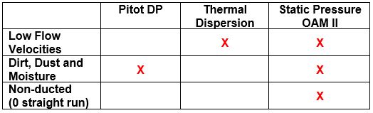
Today there are three methods for measuring outdoor airflow. The most common of these technologies are Differential Pressure and Thermal Dispersion. Let’s examine these measurement technologies along with their pros and cons.
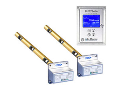
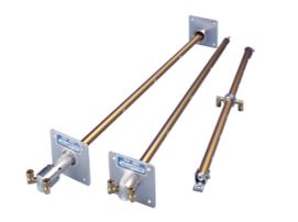
Differential Pressure
Considered the standard of airflow measurement, Differential Pressure (the direct measure of total and static pressure in the duct) has been around for many years and is widely accepted throughout many industries. An advantage of this approach is that it allows for multiple sensing points per probe and meets all ASHRAE requirements regardless of duct size.
Pros and Cons: A distinct advantage of Differential Pressure is that it has many sensing points providing a great deal of accuracy. On the downside, however, the technology was designed to be installed in a duct; and many modern buildings have ductless outside air systems. This technology may also have accuracy issues when measuring low velocity – as is typical with outside air. The Differential Pressure measurement approach reasonably resistant to dirt, dust, and moisture.
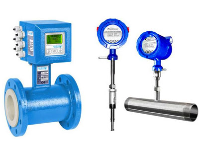
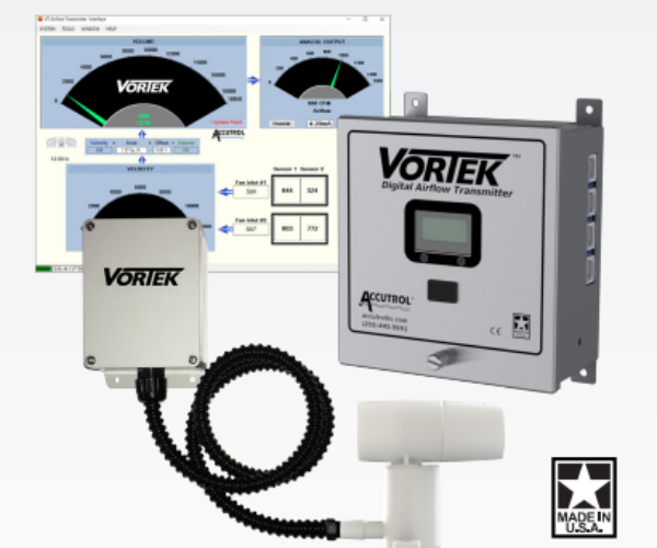
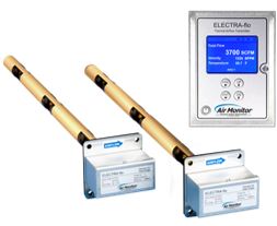
Thermal Dispersion
Another common technology for determining airflow measurement is Thermal Dispersion. Like Differential Pressure, Thermal Dispersion has been around for some time. This method utilizes two precision-matched thermistors for differential temperature measurement. One thermistor measures airflow temperature while the other is externally heated to a set differential above the airflow temperature. Heat is transferred from the externally heated thermistor to the air stream; as airflow velocity increases, the rate of heat dispersion increases. The relationship between airflow velocity and applied power is defined by an algorithmic function.
Pros and Cons: Because of its ability to accurately measure low velocity air movement, Thermal Dispersion is a great fit for outside air. Like its counterpart, this technology was developed for duct-mounted airflow measurement devices. Similarly, any contaminations such as dirt, dust and moisture will impact the impact the accuracy of the sensors.
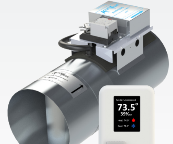
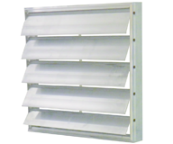
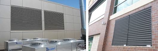
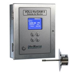
Static Differential Pressure
In this method, fixed outdoor air inlets act as a flow conditioner creating a uniform static pressure field on either side of the inlet. Velocity is determined by measuring the static differential pressure across the fixed inlet. The fixed inlet device has a unique mathematical relationship which defines the airflow velocity as a function of pressure drop. This device may be an architectural louver, rain hood with expanded metal or a prefabricated outdoor airflow measuring station. This technology is ideal for today’s buildings with non-ducted OA applications.
Pros and Cons: With the ability to measure effectively in low or high airflow velocity, Static Differential Pressure is ideal for today’s non-ducted applications. The technology is also impervious to wind gusts, dirt, debris and moisture. A fixed inlet device combined with a true static differential pressure sensor eliminates the need for straight run duct. Static Differential Pressure technology is also shown to provide excellent performance across a wide temperature range of -40° F to 120° F, and outdoor air conditions of 0% to 100% relative humidity.
Learn
More
When
it comes to measuring outdoor airflow remember this: if you’re going to measure
it; measure it accurately. We’ve just touched on the very basics of outdoor
airflow measurement accuracy.
For
a more detailed look at this topic, including installation requirements, the
formulas for calculating accuracy and measurements be sure to view the Air
Monitor Corporation free on-line webinar: “Yes You Can Accurately Measure
Outdoor Airflow”.
Refrigerant gases are literally the lifeblood of today’s air conditioning, refrigeration, and freezing technologies. Under controlled and monitored conditions these gases are safe and efficient. However, if not closely monitored and allowed to escape into the atmosphere, they can be extremely hazardous to both personnel and our environment.
To help ensure safety, ASHRAE (The American Society of Heating, Refrigerating and Air-Conditioning Engineers) mandates that each refrigerant machinery room be monitored for leaks. Specifically, ASHRAE section 8.11.2.1 states: “Each refrigerating machinery room shall contain a detector, located in an area where refrigerant from a leak will concentrate, that actuates an alarm and mechanical ventilation in accordance with Section 8.11.4 at a value not greater than the corresponding TLV-TWA (or toxicity measure consistent there with)…”
In addition to monitoring, further steps should be taken to ensure the safety of building occupants, maintenance personnel, and early responders. These include, among other precautions, external alarms, and the availability of self-contained breathing apparatus (SCBA).
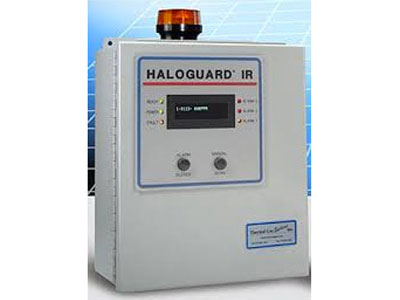
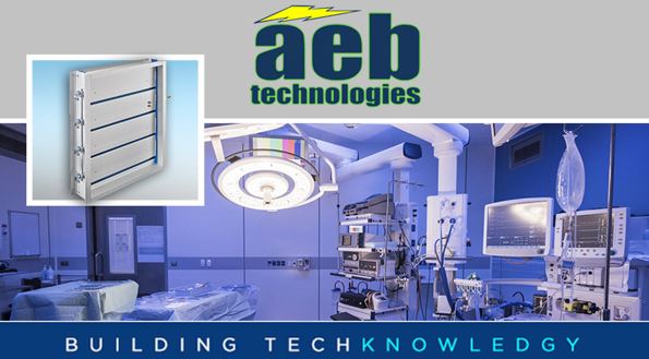
External alarm “annunciators” or “notification devices” (such as a strobe light, horn, siren) should be mounted outside of each mechanical room entryway. These alarms provide clear visual and audible alerts when air quality within a refrigerant equipment room has been compromised.
SCBAs protect against toxic fumes, or where the air has insufficient oxygen, and should be placed outside of rooms housing refrigerant equipment. Although no longer required by ASHRAE under its Standard 15-2016 (Safety Standard for Refrigerant Systems), specific requirements for respiratory protection may be required by other agencies or by local codes.
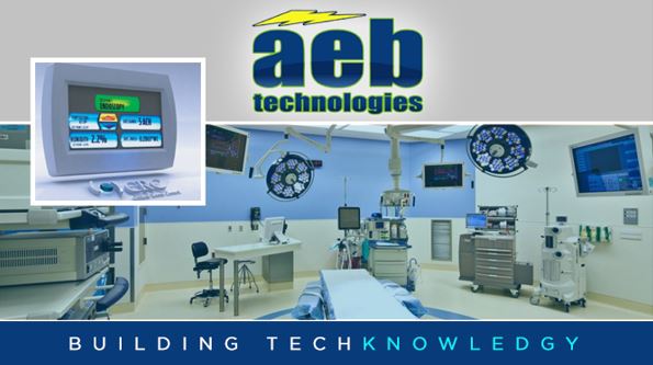
Reliable refrigerant gas monitoring is critical. Fortunately, there proven technologies available to building contractors and owners to detect and measure leaks.
Risks to Health & Environment
Leaking refrigerant gases pose a serious threat to our physical and environmental health.
Risks to Humans
Human health risks range from mild discomfort to life-threatening illness. Less severe reactions to gas poisoning include headache, nausea, shortness of breath, dizziness, coughing, vomiting, loss of coordination, and confusion. Skin rashes are another symptom, particularly for those with sensitive skin and direct contact can cause a chemical burn or frostbite.
Severe refrigerant gas poisoning can result in vomiting blood, breathing difficulties, loss of consciousness, bleeding or fluid buildup in the lungs, seizure, a burning sensation in the windpipe, irregular heartbeat, coma, or sudden death. Loss of consciousness and eventual asphyxiation from Oxygen deprivation can occur when refrigerant gas displaces the Oxygen content in closed mechanical room air.
Environmental Risks
Similarly, the leakage of refrigerant gases effects the environment. Gases that leak into the atmosphere can contribute to ozone depletion and global warming. Indirectly, refrigeration and air conditioning systems consume energy, which raises CO2 emissions contributing to global warming.
Choices are always being made by chiller manufacturers regarding cost, availability, effectiveness, public safety, and environmental impacts. For example, because of their non-flammability and non-toxicity, refrigerant gasses such as haloalkanes, chlorofluorocarbons and hydrochlorofluorocarbons (particularly CFC-11 and CFC-12) made them preferred choices for many years. However, their atmospheric stability made these gases a threat to the ozone layer. Consequently, these refrigerants were replaced with HFCs and PFCs, especially HFC-134a, which are not-ozone depleting. Yet, these gasses still pose threats to global warming and are being replaced by more environmentally friendly refrigerants.
Newer refrigerants are safer for the environment; but create concerns over toxicity and flammability. Some of today’s more popular refrigerants include:
R-134a (Tetrafluoroethane) has similar properties to R-12 but with a significantly lower potential for ozone depletion and global warming.
R-123 (Dichloro-1,1,1-trifluoroethane or HCFC-123) is used in low-pressure refrigeration and HVAC systems. Phase out of R-123 for new HVAC equipment began on January 1, 2020; it will continue to be produced for servicing equipment until 2030.
R-410a (AZ-20, EcoFluor R410, Forane 410A, Freon 410A, Genetron R410A, Puron, and Suva) is a mixture of difluoromethane and pentafluoroethane and is a preferred refrigerant for use in residential and commercial air conditioners.
(Note: R-513a and R-514a are the current replacements for R-134a and R-123 respectively.)
The Financial Impact of Leakage
In addition to presenting health and environmental risks, refrigerant leakage will have a financial impact on the business. The loss of refrigerant may cause the system to struggle to produce adequate cooling preventing buildings from reaching and maintaining desired temperatures. This not only causes the system to work harder; but will also increase monthly energy bills. An undercharged system uses significantly more energy.
Of course, there are additional expenses associated with the loss of refrigerant. These include costs such as labor to locate and repair the leak and re-charge the system. It can cost thousands of dollars to repair and replace the refrigerant in a commercial or industrial chiller. Finally, there is a cost related to system downtime. While this will vary significantly with system and application, the cost can be significant.
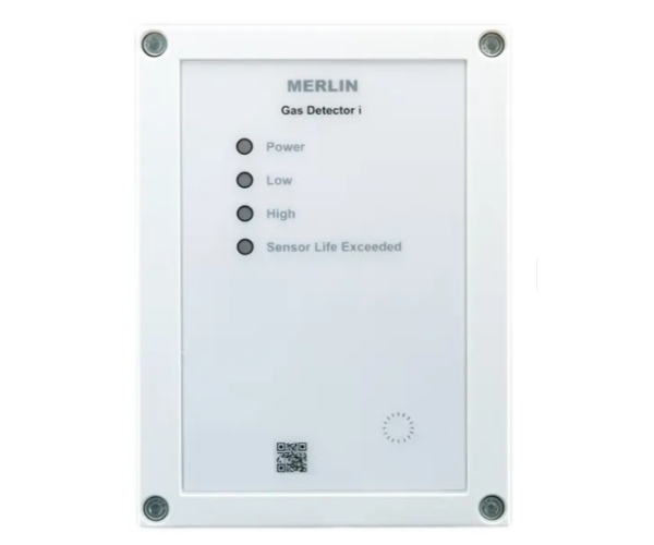
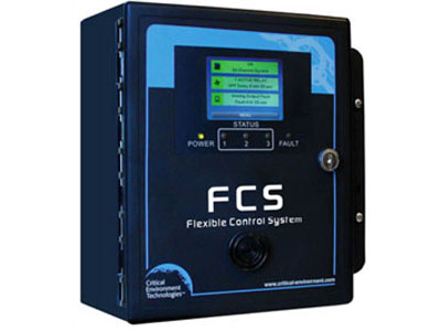
Refrigerant Gas Monitoring Solutions
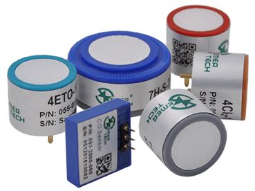
Ceramic Metal Oxide Semiconductor
Invented at Bell Labs in 1959, Metal Oxide Semiconductor technology has been around for more than sixty years. Since that time, billions of dollars have been invested in development, related technology, and instrumentation. Ceramic Metal Oxide Semiconductors (CMOS) are today a popular refrigerant gas monitoring solution. CMOS sensors will also detect gases, such as carbon monoxide, sulfur dioxide, hydrogen sulfide, and ammonia.
Within these semiconductors, sensing material is printed on an element with a heater formed on the reverse side which heats the material to several hundred degrees C. The flow of electricity inside the sensing material is determined by the number of free electrons. When the air is clean, oxygen is absorbed on the sensing material. This attracts free electrons resulting in an increase in the sensor resistance and less flow of electrons inside the sensing material.
In the presence of gases, the gas reacts with absorbed oxygen. This causes the electrons held by absorbed oxygen to be released into the sensing material. As a result, sensor resistance decreases allowing more current. As the concentration of gas increases, sensor resistance decreases further, allowing even greater current.
Advantages to this approach are that it is generally reliable, robust, cost effectiveness, relatively long-lasting, scalable, and deliver quick response times. Employed in a variety of roles and industries, these sensors are used extensively to measure and monitor trace amounts of carbon monoxide and nitrogen dioxide.
The biggest downside to CMOS monitoring is that the technology is not gas specific. Because it is cross-sensitive to many gases sensors are known to create false alarms in environments that contain gasoline, diesel, and propane exhaust or solvents, cleansers, and Volatile Organic Compounds (VOC). Disruptions associated with false readings can be time-consuming, costly, and distract building maintenance staff from other duties. Still, despite these limitations, CMOS remains a viable gas monitoring solution for meeting code requirements within a limited budget.
Inaccuracies of the sensor elements can lead to non-reproducibility of the gas attributes. CMOS calibration is therefore critical. Although the signal patterns of the various sensor elements of a production batch are quite similar, each sensor element must be calibrated to yield high analytic performance.
The importance of sensor calibration cannot be overstated. Regular calibration is the best and only sustainable method for maintaining gas monitoring system accuracy. Recalibration is not only recommended; but required to meet safety, reliability, and accuracy standards
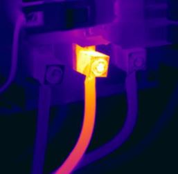
Infrared
Infrared technology can also be used to monitor refrigerant gas leaks. Discovered in the 1800s by Alexander Graham Bell, infrared technology took a quantum leap forward in 1929 when the infrared-sensitive electronic television camera was invented. In 1947, the first American thermographic cameras were developed for military use.
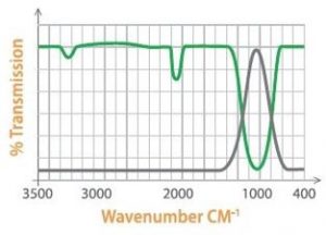
Infrared gas detection uses infrared light to detect the presence of gas. When exposed to the infrared light, the gas absorbs some of the light’s energy. Because gases absorb light energy at different wavelengths, this allows gases to be identified by measuring the absorption of light at specific wavelengths. Unlike CMOS, infrared monitoring technology is gas specific and extremely accurate.
Infrared technology comes in two forms: Absorptive (NDIR, non-dispersive infrared) and Photoacoustic.
Green represents a typical gas absorption characteristic. Gray is an infrared wavelength used to detect this specific gas.
Absorptive Infrared Technology is one of the most common forms of infrared detection. In an absorptive infrared monitor, a sample of the refrigerant gas is introduced in the measurement chamber of the device and is exposed to infrared light. At the same time, a sample of an inert gas (such as nitrogen) is present in a separate measurement chamber of the monitor.
NDIR utilizes an infrared beam passing through the sampling chamber. As this occurs each gas component absorbs some specific infrared frequency. A reference gas, typically nitrogen, is used simultaneously in another chamber. The concentration of the gas component can be determined by measuring the amount of absorbed inferred at the necessary frequency.
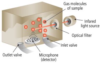
Photoacoustic Infrared Technology utilizes similar technology in that a refrigerant gas sample is introduced into a sealed measurement chambers and is exposed to a specific wavelength of infrared light energy.
Photoacoustic infrared measures an audible pulse that is generated by the refrigerant being exposed to the light. Pressure is generated inside the sealed chamber by the movement of gas molecules as they absorb the light energy. As pressure increases it is detected by a microphone inside the monitor. The extent of the pressure indicates the concentration of the gas present. A stronger pulse indicates that more gas is present. The sensitive microphone inside the monitor is sensitive and can detect even the lowest levels of gas.
What’s the Best Option?
When selecting refrigerant monitors, engineers must consider the exposure limits of the refrigerant, the mechanical room functionality and the long-term maintenance (including ongoing service) versus upfront cost.
From a pure price perspective, CMOS sensors are the least expensive option followed by Absorptive Infrared (for systems with minimal sensors) and finally Photoacoustic Infrared. An important fact to consider is that both CMOS and NDIR Systems have a higher cost per sensing point than Photoacoustic Infrared. This is due to their technology being located at the point of sensing rather than in the electronics cabinet as with Photoacoustic. Systems with greater than 3 sensing points (some refrigerants require 2 per chiller) will quickly erode this advantage and Photoacoustic Infrared technology will gain both price and performance advantage.
While the choice is yours, we highly recommend Photoacoustic Infrared Systems. We base this on their ability to provide the highest level of protection, the earliest possible alerts, the lowest required maintenance and the greatest flexibility of all of today’s available technologies.
Need Help?
AEB Technologies is here to help you make informed decisions. We can help determine the optimal refrigerant gas monitoring system for your specific application and budget. We work closely with leading HVAC manufacturers and our Instrumentation and Controls focused line card includes some of the industry’s best metering, monitoring and equipment solutions for energy-efficient campus and building management.
Recalibration is vital to sensor performance and accuracy; and AEB is your partner for expert calibration. Our calibration services keep your gas monitoring system operating efficiently and aligned with the exact specifications of its manufacturer.
We are happy to help with any questions or comments that you may have about our manufacturers or equipment. Contact us here.